Posts

November 15, 2017 - Week 13

This week I reviewed a couple of my current design ideas. The cable idea for the trussing system has now been scrapped, as compression forces will need to be accounted for. The top running beam is too small and flimsy to be able to carry load on its own. Therefore I will need to revise my previous X-bracing design to maximize strength while minimizing the volume. Other design changes and new designs I have been working on have been the vertical column supports and clamps, as well as making a mounting bracket for the track to attach to the horizontal crossbeam. The difficult part of this task is to determine where the placement of the bracket should lie. As the vertical hangers are very small and have few mounting holes, figuring out the size and orientation of these brackets will be difficult to visualize. After these two parts are completed, I will be able to run a stress analysis on the whole assembly to determine if there are failure points and what may require reinforcements.

November 8, 2017 - Week 11 & 12

The past 3 weeks I have been working on revising my current design. Originally the trussing for the vertical bracket supports involved sheet metal cutouts which assembled into an X-bracing design. With the suggestion of cost and weight reduction, these braces are now going to be redesigned as cables. The cables will be able to handle similar tension loads, while reducing the costs of fabricating sheet metal. For the vertical columns, a smaller mount and vertical supports will be designed to make the two columns stand closer together. This is done in order to accommodate narrower roadways and paths. The top column has also been modified so that the beam lays flat against the vertical columns to accommodate solar team's designs. I will continue revisions of these parts, while also create a vertical mounting bracket that will hold the tracks.

October 25, 2017 - Week 9 & 10

This week and last week was the second presentation of our project. In our presentation I displayed my current progress in the column design, footing, as well as the trussing. We also presented our analysis through Ansys to show which parts will need to be revised. Currently I am on schedule and about halfway done in creating the drawings. I will now need to revise some of my current drawings, as well as create clamps and mounts for the top beam and track connections.

October 11, 2017 - Week 7 & 8

Image
Milotek has not given us the full drawings on the vertical columns as well as the track yet. I have decided to start producing drawings for the trussing as well as creating a layout of the columns. So far, these are the designs I have created: The top shows the original design I had in mind for the cross bracing of the vertical supports. However, I realized that this will use a lot of material, and the manufacturing process of this would be extremely difficult. I decided to create the two below drawings, which feature multiple parts. The cross structure is reversible, so it can be manufactured/installed more easily. While there are more parts to be made in the second design, it prevents a lot of wasted materials as well as making it easier to manufacture. I have also started to work on the vertical columns for the track and have nearly finished. What's left is to create a clamp design that will support the horizontal beam to the vertical columns, as well as clam...

October 4, 2017 - Week 5 & 6

Image
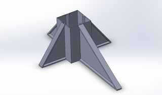
Week 4 and 5 have been on presentations of the specific groups in the Spartan Superway project. Today, we signed an NDA with Futran to obtain their drawings for their project in South Africa. We will be using these drawings to understand the parts coming in and the overall construction of the railways. However, the drawings we received were outdated, so we will have to see next week whether or not there will be more drawings. For now, I will work on creating the guideways, vertical supports, and the footings of our track. So far, this will be a rough idea on how the footings and vertical supports will look, which can be seen below. The vertical columns will be fitted in place of these footings. Other designs have been looked into, and I may modify this as we move along with the project. For the railways, we are hoping to get them verified on which drawings we will actually be using so that we can modify and improve on the structural integrity of the tracks, along with add...

September 20, 2017 - Week 4

Image
Today my team (Full-Scale Track Section) gave a presentation for the rundown on our specific project. We discussed past research, problems to overcome, project planning, and many other design obstacles that we will need to consider for our team. Below is the full presentation: After the presentations, we discussed with Ron Swenson about the project specifications and has mentioned that the SolidWorks drawings will be uploaded later this week. During the meeting, Ron mentioned the possibilities of integrating certain infrastructure like water pipes, power cables, and other tubing on the outsides of the vertical supports. There will also need to be diagonal bracing/trussing along the vertical supports. In addition to these requirements, the track will need to be designed so that it can be easily assembled and disassembled. This will make things easier later on during production when we will need to constantly adjust sections, and add parts during assembly of other team's par...

September 13, 2017: Week 3

Image
We are currently still waiting on the CAD drawings from Dr. Furman. Hopefully we will be able to get the drawings by next week and begin to start looking at the railings and drafting some parts. During the discussion of our full scale model, a couple key points came up about the structural integrity of the railings. In this discussion, Dr. Furman realized that having vertical supports every meter to hold the railings together would not be efficient enough to carry the weight of multiple or even one fully loaded tram. Because of this, we are planning on implementing trusses that will support the upper and lower beams more effectively and distribute the weight as if it was a thicker solid rail. This also brought up another similar topic on the weight distribution of the support columns. As we are only planning on doing one side of the track, the T shaped column will be split in half forming an upside-down L. This will put a lot of force as well as moment on the top beam as well as th...